BIM Test At ASHRAE HQ

Architects have long embraced BIM, and software developers are moving to add mechanical, electrical and plumbing to the models. ASHRAE Technical Committee 4.1, Load Calculation Data and Procedures, prepared a seminar for the 2010 ASHRAE Annual Conference to examine the state-of-the-art for using building information modeling (BIM) for load calculations, including methods of extracting data from the BIM model for import into traditional stand-alone calculation programs and use of built-in “native” BIM load calculation software. This article addresses native BIM load calculations only, although lessons learned regarding interoperability and data definition apply to both approaches.

Test Case: ASHRAE HQ

The ASHRAE Headquarters building in Atlanta recently underwent a major renovation and expansion. The building interior was gutted, and a conference center wing was added on the first floor. Although portions of the building exterior skin were retained, the insulation was enhanced in walls and in the roof. Interior lighting loads were reduced, and all new high efficiency mechanical systems were installed.

The Headquarters building was chosen as the test case for use in this examination of BIM load calculations based on the assumption that all data would be readily available and so the results could be used in updating the master example in the 2013 ASHRAE Handbook—Fundamentals load calculation chapter.

The first step in the process was to obtain the BIM model from the architect who designed the renovation/addition. The design was almost two years old, and BIM files had to be retrieved from archives.

Interoperability: Using IFC Files

The first challenge was discovering that the BIM software used by the architect was different than any of our seminar participants possessed. However, that software had the capability of exporting BIM data to a neutral-format Industry Foundation Classes (IFC) file. There has been significant effort on the part of BIM software vendors in recent years to develop interoperability between different BIM platforms. IFC files have been touted as the basis of that ability to exchange data.

When importing the IFC file from the architect, hundreds of error messages occurred (477 in all). These were mostly the result of elements not being precisely joined. Since the project was a renovation, and no BIM model existed, the architects created the building shell model from old “as-built” prints. This process is laborious and imperfect, so elements (such as walls, windows, column surrounds, etc.) that appeared correct on plots were actually slightly disconnected in places. Each error had to be reviewed, in order, and direction given to the IFC import module.

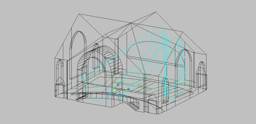
Once the error messages were resolved, the newly created BIM model “looked” good. We could rotate the view in 3-D and see a good representation of the renovated Headquarters (Figures 1a and 1b) and produce 2-D floor plans that, on the surface, looked like the construction documents.

Once the import of the IFC file was complete, spaces were defined for the load calculation process. While touted as an automated process, it was fraught with problems. The BIM model derived from the IFC required lots of additional cleanup to eliminate extraneous lines and to properly define intended enclosed spaces. Likewise, objects from the IFC file, such as tables and chairs, were sometimes interpreted by the BIM software as spaces instead of furniture. Those had to be manually deleted.

Silver Tolerance

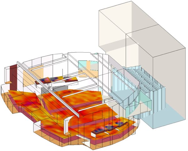
In the process of space definition, we learned a new term: “sliver tolerance.” Because BIM models are so precise, the software assigns a “space” to every enclosed volume. So restroom plumbing chases were defined automatically as spaces (Figure 2). Something as thin as a wall-mounted whiteboard in a conference room was identified as a space. The “sliver tolerance” in the input had been set too low. By adjusting that value up, the false spaces were eliminated.

Architectural Spaces Differ from Mechanical Spaces

Once the BIM software executes its automated space definitions, further manual adjustment is required for heating and cooling load calculations. In the new conference center wing of the headquarters, a large room is subdivisible by movable partitions into three smaller training rooms. Since each of those smaller rooms has different exterior exposures, the load must be calculated for each space, not as a single combined large room. This requires manual revision of the BIM space definition. The same is true where a large open office space must be subdivided manually into “interior” and “perimeter” spaces for load calculations.

Plenums

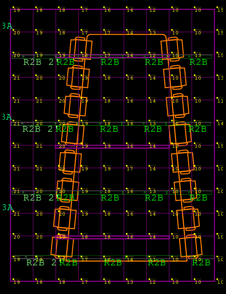
The BIM automated space definitions created spaces for ceiling return air plenums. In most stand-alone load calculation programs, plenums are treated in association with individual occupied spaces. However, the BIM software created plenum spaces based on the defined walls, which extended structure to structure. Areas where partitions did not extend to structure are merged and treated as one big plenum space (Figure 3). While logical physically, this approach doesn’t allow “% to return” assumptions for individual room lighting loads; instead those loads must be aggregated by hand for input to the composite plenum space. This is certainly doable, but is an illustration of the learning curve for the BIM model approach vs. traditional practice.

Internal Load Input

While lighting fixtures appeared in the IFC-generated BIM model, no load data (watts) were associated with those images (which were there just for the architect’s reflected ceiling plans). This was understandable given the IFC process. However, even in the native BIM software, where lighting is input as part of the active electrical model, including detailed load characteristics, the BIM load calculation module does not access the data in the electrical lighting layout. All lighting load data had to be manually input for each space for load calculation purposes (Figure 4). The same was true for people and office equipment loads.

Default Assumptions

Another difference in using native BIM load calculation software vs. traditional stand-alone programs is that the BIM software included a large number of built-in default assumptions, especially for internal loads. Most engineers are accustomed to a methodical step-by step process where each input is determined by the user based on the best information available at the time. With the BIM software, many assumptions are built in based on pre-defined building “types.” While this approach could be very helpful in providing a quick evaluation of some projects, it’s very dangerous for detailed load calculations in more sophisticated facilities. It would be very easy for an inexperienced user to “punch the button” and receive results that are very inaccurate.

Finally, BIM Load Calculation Results

After the arduous process described previously, we finally completed a BIM model with spaces defined appropriately for heating and cooling load calculations and executed the load calculations built into the BIM software. Review of the calculated overall building loads looked alarmingly low.

On examination of a few individual spaces, it was quickly determined that no loads were included for the building envelope, not for walls, windows or roof. The IFC file included surfaces labeled as walls, windows, etc., but those were not recognized by the native BIM calculation software. After trying for two days to work around the problem, including “redrawing” the exterior surfaces and defining them as such within the BIM model, we never were successful in modifying the IFC model to the point that the exterior skin load was recognized.

Punt!

At that point the deadline for the seminar submittal was approaching and drastic measures were needed (not unlike a real building design deadline). So, we punted! The IFC translated model was abandoned, and we created a “from scratch” new native BIM model based on the dimensions provided on the construction drawings. In hindsight, we should have done that from the start. The effort to clean up the IFC model far exceeded the time to create a new clean native BIM model.

The new model was created in two days by an architect experienced with the BIM software. While some simplifications were done to save time (mostly squaring off the triangular shaped exterior column surfaces), all of the plan elements affecting load calculations were included. Using the new BIM model and inputting data previously gathered for the IFC generated model, we generated the thermal model illustrated in Figures 5, 6 and 7.

First Runs

The initial execution of the load calculation module was much more reasonable than that generated from the IFC model. All exterior skin surfaces generated calculated loads; however, on more detailed review, they were not consistent with the high performance expected from the renovated facility. This was due to default program assumptions for wall construction, windows and roof insulation.

When trying to override the default data, we found that the input method was a selection from a menu of various wall constructions (Figure 8). Although the menu items were descriptive, the actual data for each element (mass, R-values, surface absorptivity, etc.) were not indicated, nor was a method available (at least that we could find) to input actual detailed construction values. The user is forced to select the “closest” fit based on a text description. There was no way to verify what actual data was used in the calculation. Again, while helpful for a “quick and dirty” analysis, this is not appropriate for detailed calculations on which the entire mechanical system design is based.

Ventilation Load: What Ventilation?

After adjusting the assumed envelope data to more realistic values, the BIM load calculations began to look more reasonable at the space level. However, the overall building loads still were well below what was expected. It turns out that although the program included all kinds of default assumptions for envelope characteristics and internal loads, it included zero outside air for ventilation.

As mentioned previously, most load calculation users are accustomed to a methodical step-by-step input process where the data is requested and if a default is assumed by the program, its value is indicated so the user can make an informed decision on whether it is acceptable or should be adjusted. This process is missing in the BIM calculation process, and becomes a post-run forensic exercise to ferret out.

After adding reasonable ventilation rates, the final run resulted in a calculated load of 69 tons (243 kW), about what had been expected for the expanded and renovated facility. At that point, we had basically exhausted all time available prior to the seminar.

BIM Loads Summary: Pleasure

What were the positive results from our efforts? BIM models produce impressive graphics. The models can be rotated in three dimensions and color coded to make great presentations. Due to the many embedded default assumptions, BIM load calculations can be executed quickly if the architectural model is conducive, and the defaults are close to the real building characteristics.

Bim Loads Summary: Pain

Unfortunately, based on the experience from this exercise, BIM has been overhyped in sales efforts by the developers. Interoperability, at least as defined by the use of IFC files has a long way to go in terms of real usability. The IFC effort successfully transferred graphics, but was not good for generating a usable thermal model.

Even the native BIM models created by architects on the same software platform require lots of tweaking to create a usable thermal model.

The workflow using native BIM calculation software is significantly different than traditional programs. This can result in incorrect defaults slipping past without the users realizing. Engineering documentation was severely lacking. We were unable to determine what methodology was used by the program, nor in many cases, the underlying data that was that used in the calculation. Was it from ASHRAE Handbook?

Reports generated by the native BIM calculations were voluminous and difficult to follow. Concise reports illustrating input data for a space along with the calculated results were not provided, making it much more difficult to ferret out erroneous inputs/results.

BIM Loads: Conclusions

Native BIM load calculations are still far from an everyday production tool. They need considerable improvement, both on the input interface and the output presentation side before most professional engineers will feel comfortable designing systems based on the results and being willing and/or able to stand up and defend their work in court, if necessary.

There is no doubt that use of the rich volume of data that could be inherent in a BIM model eventually will be of great use in reducing the tedious gathering and inputting of data into traditional load calculation programs. We all look forward to that, but further development and education is needed before we will benefit from the over-hyped theory becoming reality.

TC4.1 is working on a follow-on test effort to present in a seminar at the Montreal ASHRAE annual conference in June. That will use newer improved versions of BIM software, as well as start with a “cleaned up” native BIM model of the ASHRAE Headquarters to avoid the many problems resulting from IFC conversion described previously. Alternate methods using export of data to more traditional load calculation programs will be compared to the native BIM calculations. Hopefully, that seminar will present more positive experience and demonstrate advancements in use of BIM for load calculations.


“BIM Test at ASHRAE HQ” was published in the April 2011 edition of theASHRAE Journal.
Author: Steven F. Bruning, PE

Share This: