HVAC Design for Sustainable Lab
HVAC systems in a typical laboratory facility can use five to 10 times as much energy as the systems in a typical office building.1 This higher energy use is due to many factors including 100% outside air systems; 24-hour-a-day operation; high internal heat gains; high air change rate requirements; equipment exhaust requirements; and high fan energy.
With this significant energy use, the incentive for creative sustainable design grows. Systems or system options that have lengthy paybacks in other facility types are more likely to provide attractive and acceptable returns on investment in a laboratory facility. Additionally, many laboratories are constructed with a long-term view by owner-operated institutions that not only can accept a longer payback period but who are committed to developing sustainable facilities. The spending trend shown in Figure 1 suggests an increasing pressure to renovate existing laboratories and construct new facilities.2 In addition to the growth in total research, organizations including universities, government agencies, and private research institutes compete for the same small group of talented researchers and use new and better facilities to recruit. Given the large number of laboratory facilities that will be constructed in the next decade, it is essential to minimize the energy use of these facilities to reduce operating cost, energy dependence, and greenhouse gas emissions.
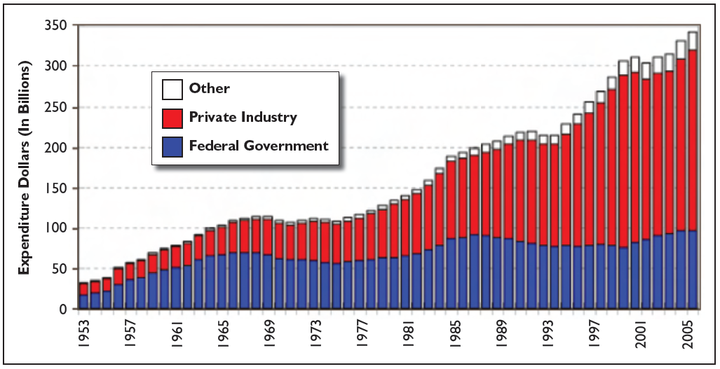 Figure 1: Research spending adjusted to 2006 constant. Courtesy AAAS. Figure 1: Research spending adjusted to 2006 constant. Courtesy AAAS.
|
Water – The Other Resource
Although HVAC energy use is often the primary focus, another important part of sustainability is water conservation. In a sustainable facility, water use is minimized and water recovery is a priority. Sustainable features such as low-flow plumbing fixtures, dual-flush flush valves, extensive circulation of domestic hot water, and rainwater recovery for nonpotable reuse are appropriate for nearly every building type. Some features of laboratory facilities offer additional water-saving opportunities. Two specific areas are process cooling and cooling coil condensate recovery.
Many laboratories house equipment such as nuclear magnetic resonance spectrometers, environmental room lasers, condensing units, and vacuum pumps that require process cooling water. Many locales permit the use of once-through domestic water—where domestic water is used and then discharged into the sanitary system—for process cooling. This should be avoided in new facilities and should be given high priority for upgrade in existing facilities. In lieu of once-through water, a recirculating process water system using building chilled water directly, a blended secondary chilled water loop, a dedicated process chiller and loop, or condenser water, should be considered based on the process water loads and other building infrastructure. Providing domestic water as an alarmed backup system is a reasonable approach to increase redundancy and reliability for sensitive or critical loads.
With high quantities of outside air and 24 hours per day operation, the cooling coils in laboratory facilities can provide a significant source of water, which can be used for a variety of purposes including irrigation or a nonpotable water supply for toilet flushing and/or cooling tower makeup. For example, in a recently built laboratory in Atlanta, four 30,000 cfm (14 158 L/s), 100% outside air air-handling units were located in a penthouse. Using weather bin data information and an estimated cooling load profile, the estimated condensate recovery from the cooling coils exceeded 800,000 gallons (3 million L) per year, with a maximum flow of 19 gpm (1.20 L/s) (Table 1).
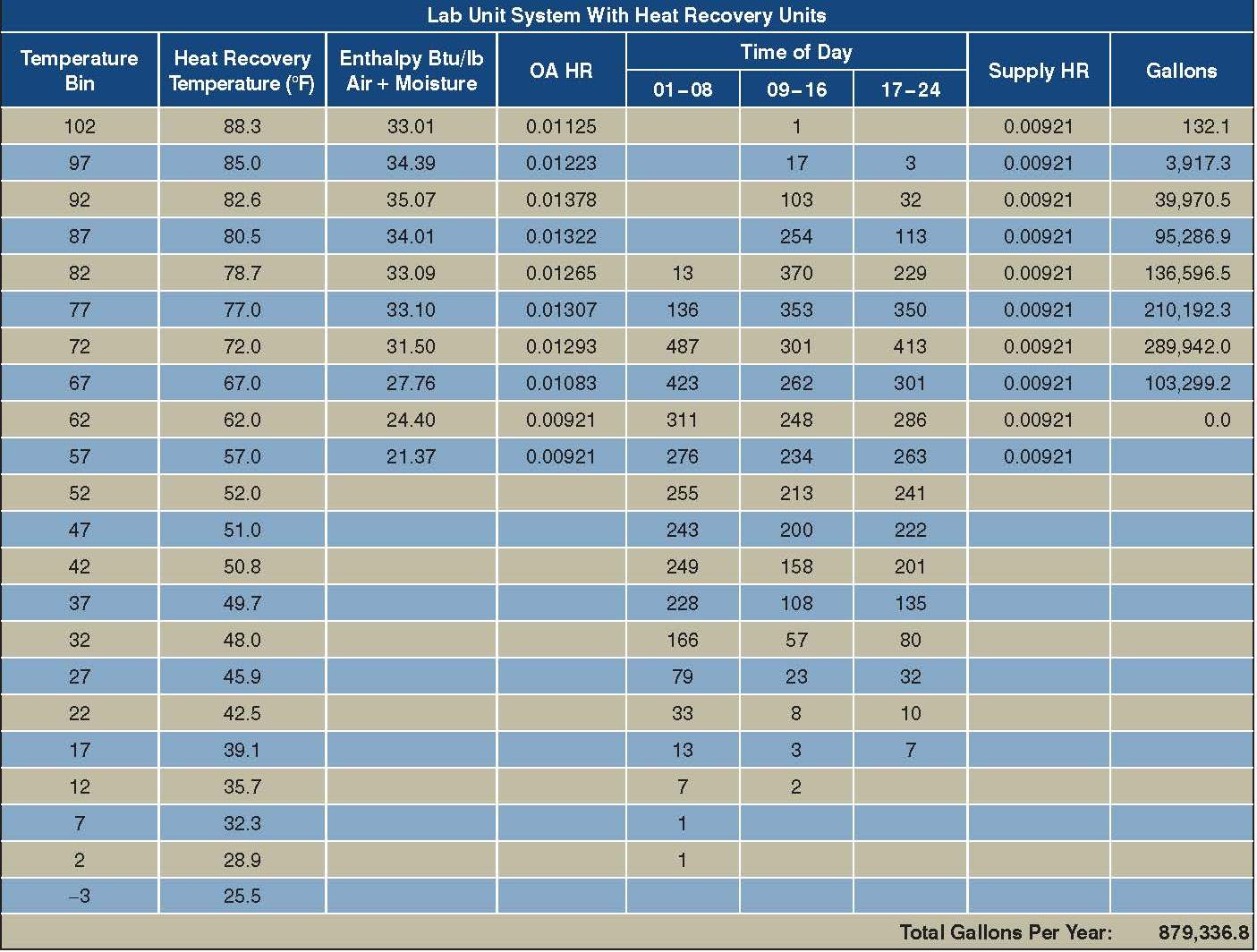 Table 1: Condensate recovery (Emory Winship Cancer Institute 3/19/2004) Table 1: Condensate recovery (Emory Winship Cancer Institute 3/19/2004)
|
In this project, the cooling towers were located at a lower elevation than the air-handling units. The collected condensate could gravity drain to the cooling tower basin, where a three-way valve directed condensate to the tower basin to make up losses from evaporation, drift, and bleed. If condensate production exceeds the cooling tower needs, the excess condensate is directed to the sanitary sewer system. If the condensate is inadequate to make up the cooling tower needs, the domestic water system provides the necessary flow. As an added benefit, the condensate is cold, lowering the condenser water temperature and cooling tower fan energy required to reject chiller heat.
Cooling coil condensate could also be used for irrigation, sometimes in conjunction with rain water capture and reuse. An attractive aspect of the condensate flow is that, in humid climates, it is available even in a drought when irrigation needs are highest.
Air-Side Savings
The most significant opportunities for reducing the environmental impact of laboratory facilities are in the air-side design. Given the number of variables of function, user criteria, climate, and systems, it is impossible to cover all the features or ways to design a sustainable laboratory. The design must be customized and tailored for the specific application. However, with respect to laboratory air-side systems, a sustainable design should focus on three main goals:
- Reduce the amount of outside air used to meet cooling and ventilation requirements;
- Recover energy from the outside air that must be used; and
- Minimize the amount of energy required to distribute air.
Reducing Outside Air Used for Cooling and Ventilation
Nothing reduces the long-term energy use and environmental impact more than reducing the amount of outside air used to meet the cooling and ventilation requirements. In a typical office building, the amount of outside air is dependent primarily on the ventilation requirements for people. In a typical laboratory facility, on the other hand, the amount of outside air has three drivers: cooling load, exhaust makeup, and industry-expected minimum air change rate. With each of these drivers, several ways exist to attack and optimize the system. Each must be addressed, since the amount of outside air used is dependent on all of these items.
Reducing the Cooling Load
Reducing the cooling load that is served with outside air should be the highest priority in a sustainable laboratory. This can be achieved via three methods: reducing the actual cooling load, using nonoutside air sources, and creative air distribution.
Reducing the actual cooling load in the laboratory is an excellent first step to achieve air-side savings. With smaller loads, a smaller HVAC system may be used, reducing not only energy use but also the capital cost, materials, and energy to install the system. When reducing the actual cooling load, there are some items that are relevant in any building and others that are laboratory facility specific. The general building issues take an added importance in the laboratory due to the hours of operation and the typical use of 100% outside air for supply. Building envelope, especially fenestration and shading, should be carefully considered.
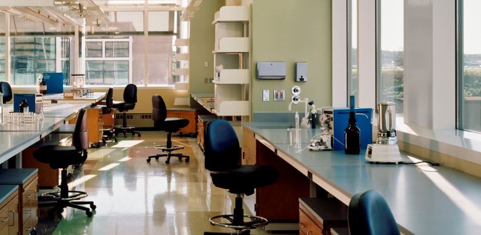
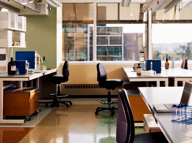
Daylighting, using natural light to illuminate a space and reduce electric light use, is a common laboratory feature3 (Photo 1). Reducing the overall illumination levels and using task lighting at work surfaces can also reduce the actual cooling load. With careful architectural design and fenestration selection, heat gain from the envelope and lighting can be reduced.
A laboratory specific issue is rightsizing the system. Often laboratory facilities, in the absence of specific criteria, are constructed with a high allowance for user equipment, such as 10 W/ft2 or 15 W/ft2 (108 W/m2 or 161 W/m2). This is done based on historical practice and for flexibility. Research by the Lawrence Berkeley National Laboratory4 suggests that actual equipment loads in laboratories are typically lower, resulting in oversized systems and energy waste. Although designers should meet the user’s criteria and provide the desired flexibility, we should also evaluate what is actually required without undue excess.
Variable air volume (VAV) systems should also be used when possible to reduce the laboratory system cooling load by reducing supply airflow to match laboratory space load. While inappropriate for some spaces, such as high containment facilities, VAV is appropriate for many facilities, including those with highly variable cooling loads, low fixed equipment exhaust requirements and low minimum air change rates, and spaces with a high fume hood density.5 ANSI/ASHRAE/IESNA Standard 90.1-2004, Energy Standard for Buildings Except Low-Rise Residential Buildings, Section 6.5.6.1, requires either VAV or heat recovery for 100% outside air systems more than 5,000 cfm (2359 L/s). The designer of a sustainable laboratory should consider using both where appropriate.
Another way to reduce the actual cooling load is with laboratory equipment consolidation and placement. Laboratories often are designed as flexible spaces with general criteria rather than specific requirements. The actual users and their research program may not be known during facility design and, even if 2008 they are known now, they will change in the future. Rather than designing the entire facility with the flexibility to accommodate heavy heat producing equipment, such as ultralow-temperature freezers or centrifuges, this equipment could be consolidated into a few smaller equipment spaces. These spaces could have high watt density criteria, while general laboratory spaces would use lower watt density criteria, ultimately reducing the overall design load. Locating heat-producing equipment in areas where high supply airflow quantities already are required for exhaust fan makeup or minimum air change requirements makes dual use of the supply air and reduces the need for reheat. Reducing the actual cooling load, when using 100% outside air for cooling, is critical in any sustainable laboratory design.
Although reducing the actual cooling load is an important first step, once the load is minimized, another approach to reducing the amount of outside air used for cooling is to use non-air sources to meet as much of the cooling load as possible. For example, with the previously discussed consolidation of laboratory equipment into an equipment room, the resultant space could have a tremendous watt density, perhaps 50 W/ft2 (538W/m2), and a corresponding high amount of cooling air would be required to serve the space. While the consolidation can provide design load reduction savings over a distributed approach, significant energy use reductions can be made by using a small dedicated recirculating unit to cool most of the sensible load. Some outside air is still supplied to the space for ventilation and minimum air change requirements but the majority of the sensible load is cooled with chilled water, eliminating the penalty of using 100% outside air as a cooling source. Another approach, commonly used in Europe, but now gaining popularity in the U.S., is the chilled beam6 (Figure 2).
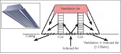 Figure 2: Chilled beam, which is a ceiling-mounted induction unit. Figure 2: Chilled beam, which is a ceiling-mounted induction unit.
|
A chilled beam is a ceiling-mounted induction unit. Primary air from a 100% outside air air-handling unit is ducted to the chilled beams and provides latent and some sensible cooling. Blended secondary chilled water at a slightly elevated temperature is piped to the chilled beams. The movement of the primary air past the beam induces room airflow through the beam where it is cooled by the coil. The result is a sensible cooling capacity with a significant, perhaps 60%, reduction in coil load and energy use. The energy reduction occurs because with a greatly reduced outside airflow, air-handling unit coil load is reduced, even though the space cooling load is essentially the same. The chilled beams have no moving parts, require no electrical connection and require no maintenance beyond an occasional vacuuming of the induction coils. Non-air sources should be considered for laboratory spaces with high sensible cooling loads to reduce energy use.
Air-distribution design and zoning offer additional opportunities to reduce the amount of outside air used for cooling and ventilation. The most obvious approach is to provide separate laboratory systems for laboratory spaces and to serve nonlaboratory spaces with systems that recirculate air and may have reduced pressure and filtration requirements. In some designs, laboratory spaces and office spaces can be intermixed, making separate systems for air distribution more difficult.
Another opportunity is using transfer air to reduce the cooling load served directly by supply air. For example, in a recent project a freezer alcove was attached to a large open lab. The general laboratory exhaust grilles for the large open lab were located in the freezer alcove above the freezers. With this significant airflow, much of the load from the freezers was captured in the exhaust air before entering the room, reducing the required supply airflow to the space and the amount of outside air used for cooling. In a similar issue, fume hoods located in small enclosed rooms increase energy use. A preferred approach is to locate hoods in larger spaces, where hood exhaust requirements more closely align with cooling and minimum air change supply air requirements or in open alcoves off larger spaces to reduce airflow. Creative zoning and air-distribution system design can be used to reduce the amount of outside air used for cooling and energy use.
Reducing Exhaust and Exhaust Makeup
A second driver in the amount of outside air used for cooling and ventilation is the airflow required to make up exhaust from laboratory spaces and equipment. Devices such as fume hoods, biological safety cabinets, snorkels, and canopy hoods are used to provide containment and local capture of odors and harmful materials and to remove heat and moisture. Equipment exhaust requirements can vary greatly between different facilities. In biomedical research facilities, there is a trend towards less chemical use and fewer exhaust devices, making it unlikely that the HVAC system and the outside airflow would be driven by equipment exhaust requirements. However, in an undergraduate chemistry lab, with a large number of fume hoods, the outside airflow would be highly dependent on the equipment exhaust requirements. Methods to reduce exhaust airflow in laboratories include VAV hoods, low-flow hoods and transfer air.
In a VAV hood, the amount of air exhausted through the hood is varied based on the sash position to maintain a constant face velocity across the opening regardless of sash position. This approach is most effective in laboratories without high constant heat loads and where there are a large number of hoods. In laboratory spaces with a small number of hoods, high steady cooling loads, or high minimum air change rates, VAV hoods, with additional complexity and cost, may provide little or no benefit. In some cases, low-flow or high-performance hoods may be a good option to reduce exhaust airflow. These hoods require a lower hood face velocity to maintain containment and may reduce makeup air requirements, depending on the lab cooling load, minimum air change requirements and number of hoods in the space. With either VAV or high-performance hoods, an analysis of the space should be performed to ensure that the features of the system provide benefit. In addition to looking at the end devices, a designer should look at the supply side.
The air requirement for laboratories is often stated as “Laboratories must be served with 100% outside air.”7 However, per AIHA/ANSI Z9.5-2003, Laboratory Ventilation, the actual requirement is that “Air from laboratories shall not be recirculated.” Recently, a new school of medicine, including a gross anatomy laboratory, was constructed. While the laboratory spaces have significant ventilation and exhaust requirements, the facility also included many offices, large lecture halls, and teaching spaces. The quantity of ventilation air to comply with ANSI/ASHRAE Standard 62.1, Ventilation for Acceptable Indoor Air Quality, in these spaces greatly exceeded the airflow required to pressurize the building. Rather than relieve this excess ventilation air, it was routed as return air to the anatomy lab air-handling unit, reducing the outside airflow for that unit from 25,000 cfm to 5,500 cfm (11 800 L/s to 2600 L/s). This had a net effect of reducing overall building energy consumption by 10%.
Another option gaining some acceptance with laboratory planners is to actually return air from labs. Laboratory designers are recognizing that a “lab” can mean many different things. For example, is it necessary to exhaust the air from a physics or laser lab? The requirement for 100% exhaust really depends on what is going on in the space and the results of the risk analysis. With increasingly sophisticated laboratory equipment, quantities of chemicals and the associated risks are being reduced in many facilities to where returning lab air from such dry lab spaces may be appropriate. Obviously, input from the laboratory planner, facility health and safety officer, and users are required to determine if returning air is appropriate. However, exhausting all air from spaces where there is no or miniscule risk to health or safety without considering options is inappropriate as we look to create facilities that minimize environmental impact.
Reducing exhaust quantity and the corresponding makeup air should be a high priority in designing a sustainable laboratory.
Minimize Air Change Rate Requirements
No single subject generates more discussion in ASHRAE Technical Committee 9.10, Laboratory Systems, than the topic of determining the appropriate minimum air change rate in laboratories. Air change rate is calculated by dividing room volume by exhaust airflow in cfm. ACH is often inappropriately used to indicate a safe level of dilution. However, AIHA/ANSI Z9.5 indicates that ACH is a poor indicator of lab safety. Technical publications such as ASHRAE Handbook, NFPA 45, Standard on Fire Protection for Laboratories Using Chemicals, and AIHA/ANSI Z9.5 provide some historically used values but these values are rules of thumb and are not based on a specific scientific basis. However, since these numbers, generally six to 12 air changes per hour, are recommended, a laboratory designer would be open to scrutiny for deviations from this range.
The goal of minimum air change rates is to ensure that, even in the case of some undefined chemical spill, some level of safety, either for exiting or spill clean up is maintained. An analysis of chemical spills of 1 L (0.26 gallon) of various chemicals charted against the number of air changes necessary to maintain the environment below the TLV, shows that for a majority of chemicals, six air changes per hour provides a safe environment. Several other chemicals exist, such as formaldehyde, where the air change rate necessary to maintain a safe environment after a 1 L (0.26 gallon) spill exceeds 50. Increasing the minimum air change rate from six to eight or even 10 provides no significant benefit in this situation, but does come at a significant energy penalty, especially in laboratories where the cooling loads and exhaust requirements are low.
ASHRAE is working with other organizations such as CDC and AIHA to explore developing a laboratory classification system that could provide some guidance to laboratory designers regarding appropriate design including minimum air change rates. Once the required minimum air change rate is defined, using setbacks to reduce the minimum during unoccupied periods should be considered.
Energy Recovery
Once the amount of outside air used to meet the cooling and ventilation requirements is minimized, the next target should be to capture energy from the exhaust streams to precondition the required makeup air. Historically, runaround heat recovery systems have been used in laboratory systems due to simplicity, flexibility and the assurance of no cross-contamination between the exhaust and makeup airstreams. Unfortunately, these systems are only about 50% efficient in capturing sensible heat and capture no latent heat. In some laboratory facilities, a better approach for heat recovery is the use of desiccant wheels. With this system, the exhaust and supply airstreams are brought adjacent to one another, and sensible and latent energy is captured via a rotating metal or fibrous wheel impregnated with desiccant material. Energy recovery wheels can have total efficiencies of about 80%. While the energy recovery wheels have improved efficiency, they also have a potential for cross-contamination of the exhaust and supply airstreams. For this reason, wheels have historically only been used for laboratory general exhaust. Fume hood exhaust and other highly corrosive or toxic exhausts were handled with separate systems, perhaps with a separate runaround heat recovery system.
Some facilities are now using energy wheels in combined general laboratory and fume hood exhaust systems where the number of fume hoods is small compared to the general exhaust requirements. In this application, it is necessary to analyze the chemicals to be used in the facility and the implications of a spill inside a hood to determine if cross-contamination would provide an unacceptable supply air condition.
Where the risk assessment shows that some chemicals or processes are inappropriate for the energy recovery wheels, some hoods connected to an independent exhaust system can be provided. While this design approach is not widespread, its use is growing.
Minimize Distribution Energy
Finally, we should reduce the amount of energy required to distribute the supply and exhaust air. Many of the options in this category apply to all building types. For example, low-pressure drop coils can be used. Variable speed drives can be used to match the system to the load. Air distribution systems should be designed for low velocity with carefully selected fittings and to avoid system effect. Laboratory specific issues include: thoughtful consideration of the exhaust system design, minimizing penalties associated with heat recovery, and analysis of exhaust stack discharge options.
In the exhaust system, exhaust devices with similar pressure requirements should be grouped together to minimize fan static pressure requirements and energy use. For example, a Type B2 biological safety cabinet has a pressure drop of about 2.0 in. w.c. (498 Pa), while a fume hood and the general exhaust grilles may have a pressure drop of only 0.15 in. w.c. (37 Pa). If a small number of devices with high-pressure-drop forces the operation of the whole larger system at a higher pressure, then energy is wasted. A more sustainable approach would be to separate the high-pressure drop systems onto a dedicated exhaust system and operate the larger system at a lower, more efficient pressure.
While designing energy recovery systems, it is wise to look for creative ways to gain additional use from the system and minimize penalties. For example, heat recovery coils in the supply and exhaust airstreams increase the system resistance and fan energy necessary to move the air. Often these fan energy penalties can reduce the energy savings and greatly increase the payback for heat recovery systems. Thoughtful design features, such as a small bypass in parallel with heat recovery coils or wheels can greatly reduce the pressure drop across the device when not in use and maximize the energy savings.
Traditionally, exhaust stacks have been designed with constant speed exhaust fans at a high velocity discharge to, along with a high stack, eject the effluent out of the recirculation zone around the building (Chapter 16 of ASHRAE Handbook—Fundamentals). This high velocity discharge can add 0.5 in. w.c. to 1.0 in. w.c. (125 Pa to 249 Pa) of pressure to the system and, with constant speed fans operating 24 hours a day, the energy use can be significant. While uncommon, multiple alternatives to the traditional approach exist including:
- Variable discharge velocity with CFD or wind tunnel confirmation of safety;
- Special discharge dampers that permit variable speed fans with constant discharge velocity;
- Multiple fans with fan staging; and
- Staging multiple stacks off a common exhaust header.
Conclusion
Laboratories require significant resources to construct and operate and the number of laboratory facilities will continue to grow. HVAC designers should consider methods to reduce a facility’s impact on the environment by reducing water use and recovering water for reuse where appropriate. While the designer’s first obligation is to the safety of the laboratory users, visitors and maintenance personnel, it is possible to creatively reduce the energy use of facilities. Reducing quantities of outside air used for cooling and ventilation, using recovered energy, and reducing distribution energy are methods to design sustainably. Together owners, users, architects, laboratory planners and engineers can find creative ways to design safe and sustainable laboratories for the future.
“HVAC Design for Sustainable Lab” was published in the September 2008 edition of theASHRAE Journal.
Author: Gregory R. Johnson, PE